| [ Q-Car Home ] [ What's New ] [ Product Listings ] [ Ordering ] [ Information ] [ About Us ] |
|
|
|
|
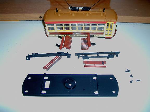
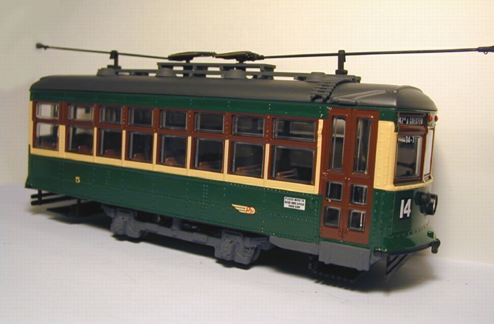
The following photos and descriptions have been contributed by Tony Tieuli. Disassembly of the Birney Car and Q-Car Power Installation
Four screws hold the sideframes and the life guard trays to the floor. Four more screws hold the life guard gates to the ends of the floor. One screw holds the truck to the center of the floor, so you have to break a glue joint to get it off. I just twisted the "truck" and it snapped off. The subfloor is attached to the upper floor by the screws just removed. A small modeler's flat screwdriver blade is inserted from the ends and the subfloor just pops out. There is an inner floor with seats and controls details molded and attached. It is held in by 2 screws, one in each headlight, It is necessary to pry the lenses out with an Xacto #11 blade. The headlight paint can be scratched off on the rim of the headlight, but it is easily touched up with basic flat black. I drilled two small #60 holes in the headlight and used a small tweezer to pry it out. Either method seems to work ok. Underneath the headlights are the screws holding the inner floor.
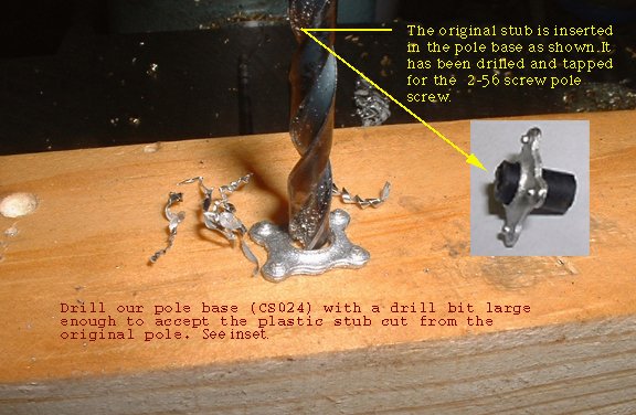
After the screws are out of the headlights, carefully pry the floor out. It is a tight fit. There are also two stanchions on each side of the car at the doors. They are locator pins for alignment. You really don't need them and they are fiddly to get in place after taking the car apart. The trolley poles can be removed. They are held on by screws into their pivots from inside. I cut off the bushings at the pole base and tap them for 2/56 screw. These can be glued in place in the roof to insulate the Q scale poles from the roof. You can replace the pole hooks if desired. (I didn't.) I reuse the two screws in the head light to hold the floor in place against the window material which forms a "stop" to prevent the floor from pushing in further. I also remove the stanchions near the doors and the two "bulkhead" type units at each end. I cut these off at seat level and leave the rest glued to the floor.
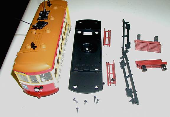
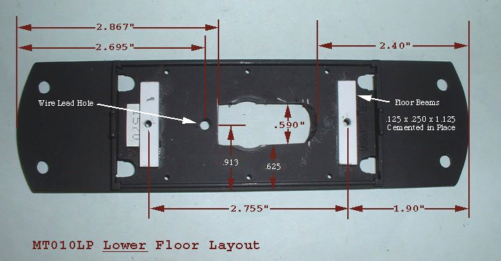
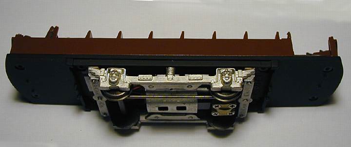
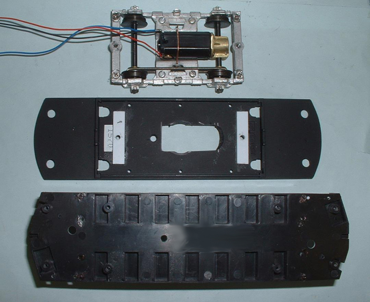
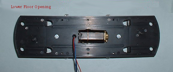
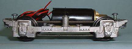
Mounting the Q-Car Company MT010LP TruckThe lower floor must have an aperture cut out to clear the motor and gear housing. I just cut a rectangular box in the lower floor. The upper floor does not have be cut to clear the top of the motor. The new flat can motor drives fit below this floor. The truck must be put on the lower floor to see how much shimming must be done so the sideframes just clear the floor rib on the outside of the floor. You may have to trim the large center spring on the truck or alternatively, cut a notch in the floor frame. I used two pieces of 1/8 x 3/32 wood and glued them in place after making sure the truck was centered. The wood fits inside the frame perfectly. The truck is attached to the floor by two screws. Drill two holes through both floors and the wood shims for this purpose and thread the screw down from the top of the floor into the truck mounting bar. Wiring can be done your favorite way. I generally take a piece of brass wire and bend it into an L shape. The short leg of the L is soldered to both poles and the long end led into a hole in the floor so it comes out underneath. I solder the motor lead to this and I am done. Reassembly of the car is straightforward and floors attached to body by the two headlamp screws. I have taken a silver sequin to replace the original headlight lens. It is quite effective and looks better than the original. Experienced modelers have their own methods of wiring, etc., so the above is only one method of doing it.
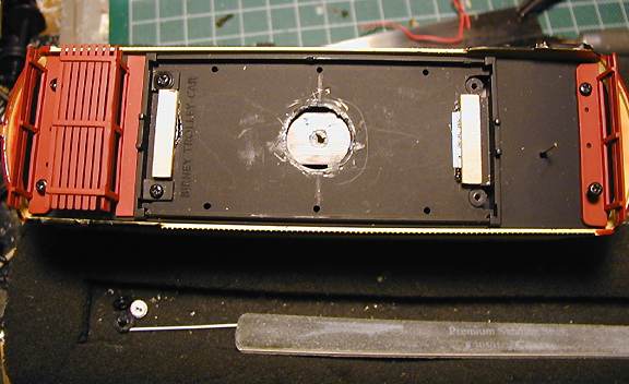
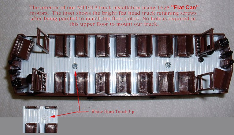
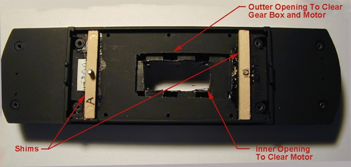
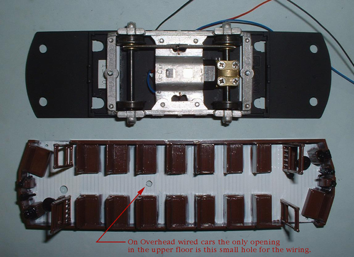
Enjoy your car! Tony Tieuli February 28, 2006 and for another way.... Mounting the Q-Car Company MT010LP Truck by Roger SomersThe following photos and description have been contributed by Roger Somers. Here is a neat way to install a Q-Car Birney truck [MT010LP] in the Corgi® Birney without cutting a hole in the inner floor. For the final appearance of the Birney, it is a good idea to avoid cutting a hole in the inner floor if you can avoid it. The Corgi® Birney has two floors. The inner floor has the seats. The sub or bottom floor is where the Corgi® truck mounts. Some initial measurements were made and it appeared as though the Q-Car Truck could be installed in the sub floor with out tampering with the inner floor. After clearing all the extra plastic out of the sub floor I centered the Q-Car truck on the sub floor and marked off where the mounting holes should go. (The truck was mounted so the gear box was at the "A" end.) Then a small rectangular hole (1/2" x 1 7/16") was cut, just enough to clear the motor, in the sub floor. In removing the excess plastic, I left the 1 3/4" x 3 3/4" frame that the Corgi side frames mounted to so the floor would retain some stiffness. Some of that structure also supports the fenders. This frame requires a notch to clear the center truck spring however. 
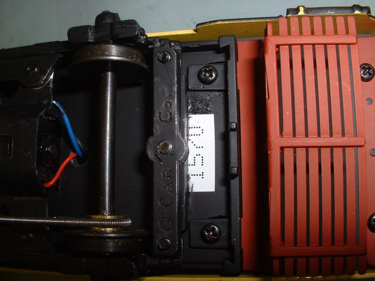
As a test, the truck was mounted to the sub floor such that the leaf springs on the truck ends touched this plastic frame. This left quite a gap between the end mounting frame on the Q truck and the sub floor but, we'll get to that later. After drilling and countersinking the holes for the mounting screws on top of the sub floor, I found the only thing protruding slightly above the sub floor was the motor strap. So, a little clearance was milled on the underside of the inner floor for the strap. Then put the Birney back together to check to see if it was the correct height off the rail or was more adjustment required. It turned out to be the correct height and I now thought about the gap between the truck frame and the sub floor to finish the truck installation. After studying it for a while, I realized that if the end frame piece on the Q-Car truck were flipped over so the side frames mounted to the opposite side of this piece, it would fill this gap perfectly and also add strength to the plastic part of the assembly. It also makes the motor accessible without disassembling the car. Just remove the 4 corner screws and the whole truck drops out. The two chrome rods on either side of the doors were discarded as well as the brown plastic "bulkhead" nubs on top that you cannot get back in place even if you tried for a week. Now all that is left is to install poles, hooks, people and wire it up. 
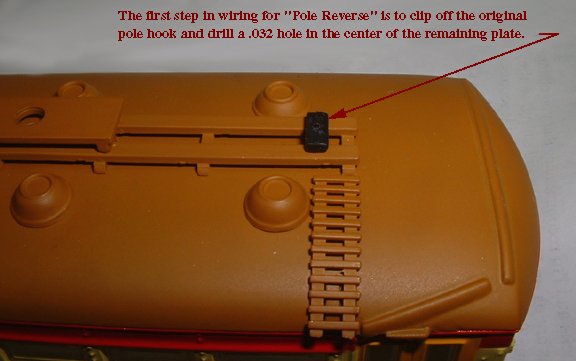
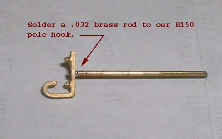
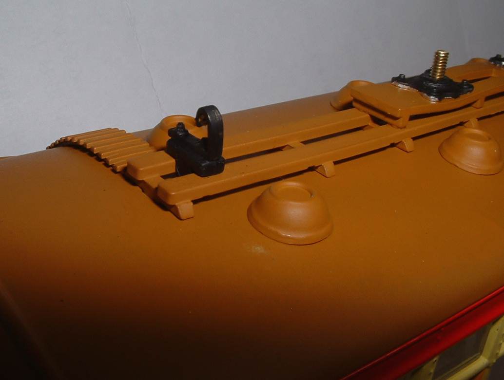
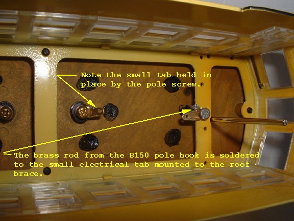
One frustration for mounting the floor assembly back in the Birney is the mounting screws behind the headlights. If the need arises to open the car up for fixing a loose figure or wire, the headlight would have to be removed again. This was solved by using the wiring from the poles and hooks to hold the floor in place. (The following wiring description is for pole reverse.) The wires from the poles and hooks were run down the wide window post on the opposite side of the car from each of the doors. Rather than fool with grounding the body, a wire was attached to both pole hooks, made from brass flat stock, and run down the side at the "A" end of the car and wires from each of the poles down at the same spot at the "B" end of the car. The wire is run in the passenger compartment in relation to the bulkheads so the bulkheads hide the wire well. A little clearance was milled on the outside of the upper and lower floors for the wire to pass through without binding against the body. Some solder terminals were added to the lower floor near the center of the car. Terminals used were small brass tacks installed from the upper side of the sub floor. One terminal for the pole hook wire on the "A" end of the floor and two terminals for the motor wiring from the poles on the "B" end. Then wire the 2 motor leads and truck frame to the proper terminals. Don't forget that the fenders need to be reattached to the floor so leave the wire long enough to clear around them. Now fold the wire from the hooks and poles over to the proper terminals and solder them. The wires also are holding the floor in place. Roger Somers - 1 May 06 Editors Note: If you follow Roger's suggestion about rotating the end truck bolsters please discard the 2-56 x 1/4" Flat Head screws that hold them in place and replace them with 2-56 x 1/4" Pan Head screws. Additional Birney Installation Photos.Some photos have captions, explaining pole mounting for "Pole Reverse" operation.
For more information about ordering either our MT10LP truck click here. All photos copyright Q-Car Company, Inc. |
| [ Back to Top ][ Q-Car Co. - Home ][ contact@qcarcompany.com ] | Page Last Modified: 23-Mar-24 3:58 PM |


